
Electric field lines of force provide a visual representation of electric fields and help explain their direction, strength, and distribution around charges and charged conductors. This article discusses the concept and definition of electric field lines, their important properties, and the relation between field-line density and electric field strength. It explains the electric field patterns of positive and negative point charges, an electric dipole, equal and unequal like charges, and a positively charged plane conductor. It also examines the inverse-square dependence of electric field strength using field-line density, followed by derivations of the electric field due to an infinitely long uniformly charged wire, a uniformly charged ring, and a uniformly charged semicircular ring. The article concludes with important conceptual questions covering test charges, the direction and nature of electric field lines, charged conductors, uniform electric fields, and the motion of charged particles in an electric field.
Electric Field Lines of Force
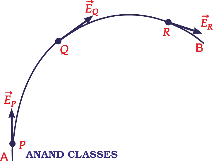
Michael Faraday (1791-1867) introduced the concept of lines of force to visualize the nature of electric (and magnetic) fields. A small positive charge placed in an electric field experiences a force in a definite direction and if it is free to move, it will start moving in that direction. The path along which this charge would move will be a line of force.
The lines of force do not really exist; they are imaginary curves. Yet the concept of lines of force is very useful. Michael Faraday gave simple explanations for many of his discoveries (in electricity and magnetism) in terms of such lines of force. We may define,
An electric field line as a path, straight or curved in electric field, such that tangent to it at any point gives the direction of electric field intensity at that point.
In fact, it is the path along which a unit positive charge actually moves in the electrostatic field, if free to do so. In Figure AB is an electrostatic line of force. The tangent to the line at any point P gives us the direction of electric intensity at P. Similarly, tangent to AB at Q gives us the direction of . The field lines are in three-dimensional space, though Figure shows them only in a plane.
Properties of Electric Field Lines of Force
1. The electric lines of force are continuous smooth curves without any breaks.
2. The lines of force start at positive charges and end at negative charges – they cannot form closed loops. If there is a single charge, then the lines of force will start or end at infinity.
3. Tangent to the electric field line at any point gives the direction of electric field intensity at that point.
4. No two electric field lines of force can intersect each other.

Reason : This is because at the point of intersection P, we can draw two tangents PA and PB to the two lines of force, Figure. This would mean two directions of electric field intensity at the same point, which is not possible. Hence no two electric lines of force can cross each other.
5. The electric field lines are always normal to the surface of a conductor on which the charges are in equilibrium.
Reason : If the lines of force are not normal to the conductor, the component of the field parallel to the surface would cause the electrons to move and could set up a current on the surface. But no current flows in the equilibrium condition. Therefore, there is no component of electric field intensity parallel to the surface of the conductor.
6. The lines of force have a tendency to contract lengthwise. This explains attraction between two unlike charges.
7. The lines of force have a tendency to expand laterally so as to exert a lateral pressure on neighbouring lines of force. This explains repulsion between two similar charges.
8. The lines of force do not pass through a conductor because the electric field inside a charged conductor is zero.
9. Electric field lines pass through dielectrics.
10. The relative closeness of the lines of force gives a measure of the strength of the electric field in any region. The lines of force are
(i) close together in a strong field.
(ii) far apart in a weak field.
(iii) parallel and equally spaced in a uniform field.
Similar concepts include Electric Field due to Point Charge, Group of Charges, Continuous Charge Distribution Numerical Problems
Electric Field Lines for different Charged Conductors
Electric field lines for different charge systems are explain as follows :
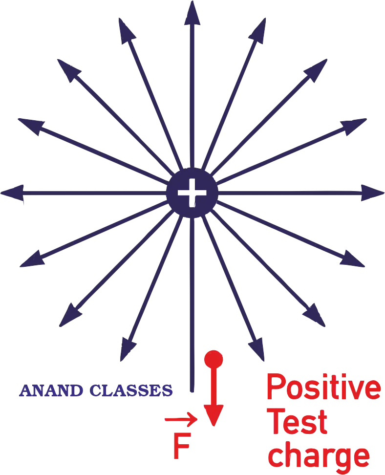
(i) Electric Field Lines of a Positive Point Charge
Figure shows the lines of force of an isolated positive point charge. They are directed radially outwards because a small positive charge would be accelerated in the outward direction. They extend to infinity. The field is spherically symmetric i.e., it looks same in all directions, as seen from the point charge.
(ii) Electric Field Lines of a Negative Point Charge
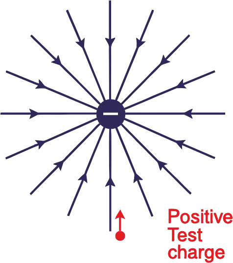
The electric field of a negative point charge is also spherically symmetric but the lines of force point radially inwards as shown in Figure. They start from infinity.
(iii) Electric Field Lines of Two Equal and Opposite Point Charges (Electric Dipole)
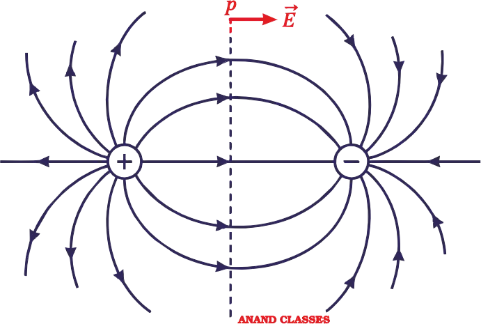
Figure shows the electric lines of force of an electric dipole i.e., a system of two equal and opposite point charges (+q, –q) separated by a small distance. They start from the positive charge and end on the negative charge. The lines of force seem to contract lengthwise as if the two charges are being pulled together. This explains attraction between two unlike charges. The field is cylindrically symmetric about the dipole axis i.e., the field pattern is same in all planes passing through the dipole axis. Clearly, the electric field at all points on the equatorial line is parallel to the axis of the dipole.
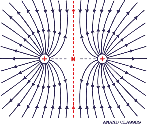
(iv) Electric Field Lines of Two Equal and Positive Point Charges
Figure shows the lines of force of two equal and positive point charges. They seem to exert a lateral pressure as if the two charges are being pushed away from each other. This explains repulsion between two like charges. The electric field is zero at the middle point N of the join of two charges. This point is called neutral point from which no line of force passes. This field also has cylindrical symmetry.
(v) Electric Field Lines of Two Unequal and Positive Point Charges
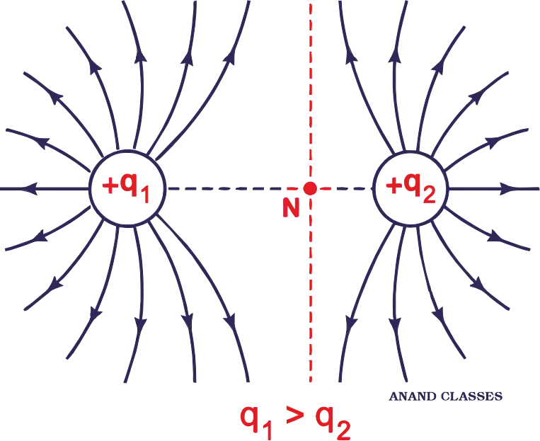
Figure shows the lines of force of two unequal and positive point charges. They seem to exert a lateral pressure as if the two charges are being pushed away from each other. This explains repulsion between two like charges.
When the charges are equal, neutral point N lies at the centre of the line joining the charges. However, when the charges are unequal, the neutral point N is closer to the smaller charge as shown in Figure.
(vi) Electric Field Lines of a Positively Charged Plane Conductor
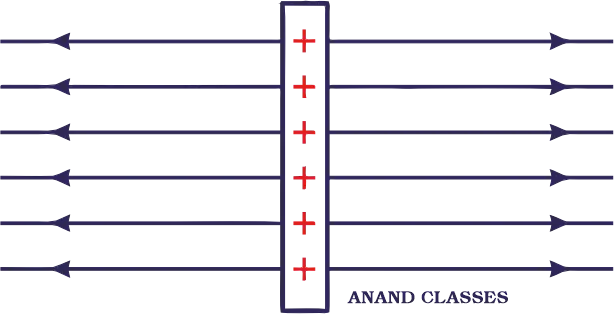
Figure shows the pattern of electric lines of force of positively charged plane conductor. A small positive charge would tend to move normally away from the plane conductor. Thus the lines of force are parallel and normal to the surface of the conductor. They are equispaced, indicating that electric field E is uniform at all points near the plane conductor.
Related topics include Forces Between Multiple Charges: Principle of Superposition Solved Numerical Problems
Relation between Electric Field Strength and Density of Electric Lines of Force
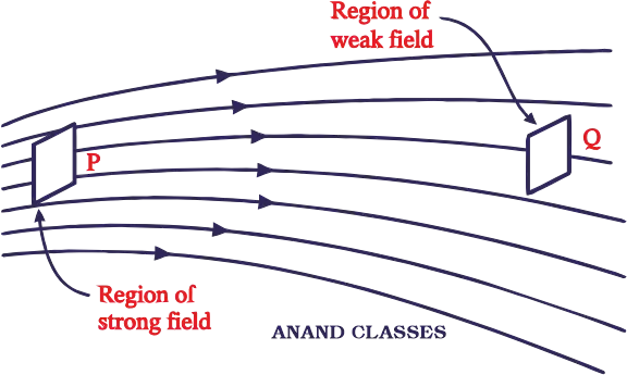
Electric field strength is proportional to the density of lines of force i.e., electric field strength at a point is proportional to the number of lines of force cutting a unit area element placed normal to the field at that point. As illustrated in Figure, the electric field at P is stronger than at Q
Consistency of the Inverse Square Law with the Electric Field Lines
The magnitude of the field is represented by the density of field lines. Near the charge, lines are closer, so the density of field lines is more and hence electric field is stronger near the charge. Away from the charge, the field lines are well separated, the density of field lines is smaller and hence electric field is weaker, away from the charge. We may, therefore, define
Electric field intensity at a point is equal to number of field lines crossing normally a unit area around that point.
As field lines are three dimensional and all figures are drawn on the plane of the paper (in two dimensions), therefore, to estimate the density of field lines, we have to consider the number of field lines per unit cross-sectional area perpendicular to the lines. We know that in three dimensions, the solid angle ΔΩ subtended by a small perpendicular plane area ΔS at a distance r from apex can be written as ΔΩ = ΔS/r2.
With a charge Q at the apex O of the cone, number of radial field lines in a given solid angle is the same. In Figure, let us consider two points P1 and P2 at distances r1 and r2 respectively from the charge.
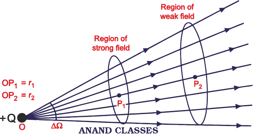
At P1, area subtended by the solid angle ΔΩ is r12 .ΔΩ. At P2, area subtended by the solid angle ΔΩ is r22 .ΔΩ.
The number of field lines cutting these area elements are the same. Let it be n.
Therefore number of field lines cutting unit area element at P1 = Electric field intensity at P1, i.e., and number of electric field lines cutting unit area element at P2 = Electric field intensity at P2, i.e., . Clearly;
i.e., electric field intensity is more near the charge and vice-versa.
Explore more concepts related to Coulomb’s Law of Electrostatics: Formula, Vector Form, Examples & Numericals
Electric field due to a Infinitely Long Thin Wire of Uniform Linear Charge Density
Consider an infinite line of charge with uniform line charge density λ as shown in Figure. We wish to determine its electric field at any point P at a distance y from it. The charge on small element dx of the line charge will be dq = λdx.
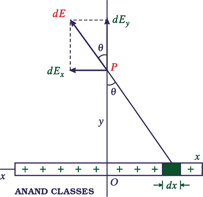
The electric field at the point P due to the charge element dq will be
The field has two components :
and
The negative sign in x-component indicates that acts in the negative x-direction. Every charge element on the right has a corresponding charge element on the left. The x-components of two such charge elements will be equal and opposite and hence cancel out. The resultant field gets contributions only from y-components and is given by
Now ,
Students should also study Electric Charge Quantization, Additivity, Charging by Induction, Solved Numericals
Electric Field Intensity at any Point on the axis of the Uniformly Charged Ring
A charge is distributed uniformly over a ring of of radius ‘a. Suppose that the ring is placed with its plane perpendicular to the x-axis, as shown in Figure.
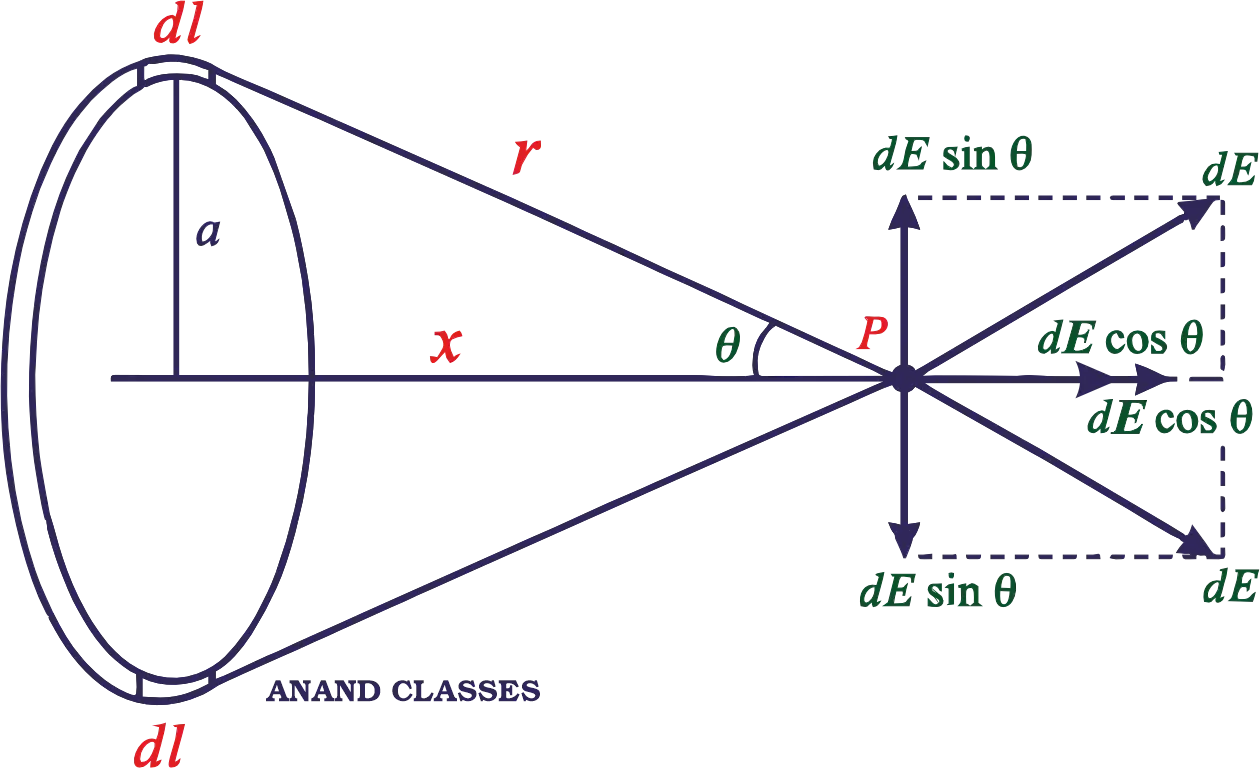
Consider a small element dl of the ring. As the total charge q is uniformly distributed, the charge dq on the element dl is
Therefore the magnitude of the field produced by the element dl at the field point P is
As shown in Figure, the field has two components :
The axial component dE cosθ, and the perpendicular component dE sinθ.
Since the perpendicular components of any two diametrically opposite elements are equal and opposite, they all cancel out in pairs. Only the axial components will add up to produce the resultant field E at point P, which is given by
because only the axial components contribute towards E
because cosθ = x/r and
Special case : For points at large distances from the ring, x >> a
This is the same as the field due to a point charge, indicating that for far off axial points, the charged ring behaves as a point charge.
Note : At the centre of the uniformly charged ring, the electric field is zero. The contributions from opposite elements cancel completely at the centre.
At center of the ring, x = 0 and E = 0.
Electric Field Intensity at the Center of the Uniformly Charged Semicircular Ring
A thin semicircular ring of radius a is charged uniformly and the charge per unit length is λ. As the total charge q is uniformly distributed, the charge dq on the element dl is
dq = λ dl
Consider two symmetric elements each of length dl at A and B. The electric fields of the two elements perpendicular to PO get cancelled while those along PO get added.
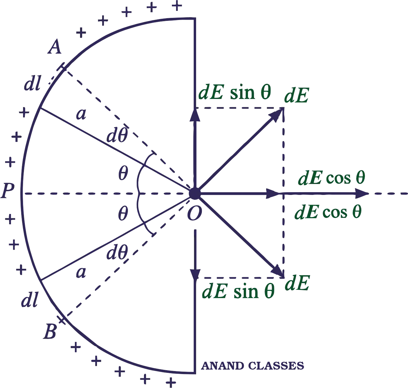
Electric field at center O due to an element of length dl is
The direction of dE is along PO.
[Since, dl = a dθ]
Total electric field at the centre O is
Short Conceptual Questions and Answers on Electric Field Lines for Class 11 Physics, JEE, NEET
Why should a test charge be of negligibly small magnitude?
The magnitude of the test charge must be small enough so that it does not disturb the distribution of the charges whose electric field we wish to measure otherwise the measured field will be different from the actual field.
In defining electric field due to a point charge, the test charge has to be vanishingly small. How this condition can be justified, when we know that charge less than that on an electron or a proton is not possible?
Because of charge quantisation, the test charge qo cannot go below e. However, in macroscopic situations, the source charge is much larger than the charge on an electron or proton, so the limit q0 → 0 for the test charge is justified.
What is the advantage of introducing the concept of electric field ?
By knowing the electrical field at a point, the force on a charge placed at that point can be determined.
How do charges interact ?
The electric field of one charge exerts a force on the other charge and vice versa.
An electron and a proton are kept in the same electric field. Will they experience same force and have same acceleration ?
Both electron and proton will experience force of same magnitude, F = eE. Since a proton has 1836 times more mass than an electron, so its acceleration will be 1/1836times that of the electron.
Why direction of an electric field is taken outward (away) for a positive charge and inward (towards) for a negative charge?
By convention, the direction of electric field is the same as that of force on a unit positive charge. As this force is outward in the field of a positive charge, and inward in the field of a negative charge, so the directions are taken accordingly.
A charged particle is free to move in an electric field. Will it always move along an electric field ? [lIT]
The tangent at any point to the line of force gives the direction of electric field and hence of force on a charge at that point. If the charged particle starts from rest, it will move along the line of force. If it is in motion and moves initially at an angle with the line of force, then resultant path is not along the line of force.
A small test charge is released at rest at a point in an electrostatic field configuration. Will it travel along the line of force? [NCERT]
Not necessarily. The test charge will move along the line of force only if it is a straight line. This is because a line of force gives the direction of acceleration and not that of velocity.
Why do charges reside on the surface of the conductor?
Charges lie at the ends of lines of force. These lines of force have a tendency to contract in length. The lines of force pull charges from inside a conductor to its outer surface.
Why is electric field zero inside a charged conductor?
This is because charges reside on the surface of a conductor and not inside it.
Why do the electrostatic field lines not form closed loops?
Electrostatic field lines start from a positive charge and end on a negative charge or they fade out at infinity in case of isolated charges without forming any closed loop.
Alternatively, electrostatic field is a conservative field. The work done in moving a charge along a closed path must be zero. Hence, electrostatic field lines cannot form closed loops.
Do the electric lines of force really exist? What is about the field they represent?
Lines of force do not really exist. These are hypothetical curves used to represent an electric field. But the electric field which they represent is real.
Draw lines of force to represent a uniform electric field.
The lines of force of a uniform electric field are equidistant parallel lines as shown in Figure.

A positive point charge (+q) is kept in the vicinity of an uncharged conducting plate. Sketch electric field lines originating from the point charge on to the surface of the plate.
Starting from the charge +q, the lines of force will terminate at the metal plate, inducing negative charge on it. At all positions, the lines of force will be perpendicular to the metal surface.
Why is it necessary that the field lines from a point charge placed in the vicinity of a conductor must be normal to the conductor at every point.
If the field lines are not normal, then the electric field would have a tangential component which will make electrons move along the surface creating surface currents and the conductor will not be in equilibrium.
The force on an electron kept in an electric field in a particular direction is F. What will be the magnitude and direction of the force experienced by a proton at the same point in the field? Mass of the proton is 1836 times the mass of the electron.
A proton has charge equal and opposite to that of an electron. Hence the proton will experience a force equal and opposite to that of F.
Electric Field Lines Properties Presentation Video
Watch the complete Electric Field Lines Properties Presentation Video to study the field-line diagrams carefully, understand the physical reasoning behind each property and use the concepts to solve numerical and conceptual problems in electrostatics.

Electrostatics Revision Notes PDF Download : Electric Field Lines of Force Properties and Applications
Master key electrostatics concepts with this comprehensive, download-ready PDF guide. Covering essential topics like Electric Field Lines and Their Properties, alongside step-by-step derivations for the Electric Field Due to an Infinitely Long Thin Wire, a Charged Circular Ring, and a Semicircular Ring, this resource is designed to boost your revision. Download the PDF below to sharpen your problem-solving skills and excel in your CBSE Class 11, JEE, and NEET physics preparation!
To download the PDF notes of Electric Field Lines Properties, Electric Field due to Infinitely long thin wire, Charged Circular and Semicircular Ring, click the Download PDF button below :